
Why Are Gate Valves Used in Industrial Applications?
Across a plant, a valve may sit on a cooling-water header, a steam line, or a process pipe that must be isolated for maintenance. Gate Valves are often selected for these duties because their gate moves clear of the flow path when fully open. This creates a relatively unobstructed passage and, in many designs, keeps pressure loss modest. In the field, a clear flow path can matter on long pipe runs and large utility lines.
That advantage has limits. Gate valves are generally intended for fully open or fully closed service, not for regulating flow. Partly open operation can cause vibration, seat wear, and erosion, especially where fluid velocity is high. They also take several turns to operate, so they may not suit applications requiring rapid shutoff. Small detail. A handwheel still needs room. That matters.
Choosing a valve involves more than matching pipe size. Engineers and maintenance teams compare pressure and temperature ratings, body and trim materials, end connections, operating frequency, and fluid properties. A valve suitable for clean water may not suit abrasive slurry or corrosive chemicals. Access for inspection and repair matters too; a valve crowded behind equipment can be difficult to service. The familiar choice is not always the right one. This guide explores why Gate Valves remain common in industrial systems, where they perform well, and which practical trade-offs deserve attention before installation.
Gate Valve Design and Operating Principle
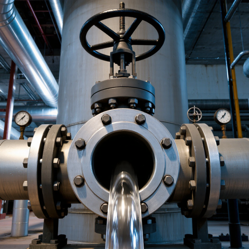
A gate valve controls flow by lifting a flat or wedge-shaped gate out of the fluid path. The gate moves at a right angle to the pipe, guided by the valve body. A handwheel turns a threaded stem; in larger systems, an actuator may do the work. When the gate reaches the bottom, its faces press against the seats and stop flow.
That sounds simple. It isn’t always. Seat alignment, pressure, and debris can affect how tightly the valve closes. Rising-stem designs show the gate’s position as the stem moves, while non-rising stems save vertical space. In either design, operators usually turn the valve fully open or fully closed. A partly open gate can vibrate, wear, or suffer damage from fast-moving fluid.
When fully open, the gate largely clears the bore, leaving a relatively direct path with little flow restriction. This can suit pipelines that need isolation and minimal pressure loss. It is less suited to regulating flow. In the field, a stiff handwheel or a small leak after closure deserves attention; forcing the stem may worsen the problem. The design is dependable when properly selected and maintained, but it is not immune to wear. A little uncertainty remains when deposits hide the seating surfaces.
| Design Feature | Operating Principle and Industrial Benefit | Application Consideration |
|---|---|---|
| Sliding gate or wedge | A gate moves across the flow path. When fully raised, it leaves a nearly unobstructed passage, making the valve suitable for on/off isolation. | The valve should normally be operated fully open or fully closed, rather than used to regulate flow. |
| Low obstruction when open | With the gate clear of the flow, a full-bore design can produce relatively little flow resistance and a small pressure drop compared with more restrictive valve arrangements. | Actual pressure loss depends on valve design, size, and operating conditions; it is not zero. |
| Multi-turn stem | Turning a handwheel or actuator moves the stem and gate gradually, allowing controlled opening and closing of the isolation device. | The longer travel generally makes operation slower than quarter-turn valves, which can be useful where gradual isolation is preferred. |
| Wedge gate | A wedge-shaped gate seats against matching valve seats to shut off flow. This design is common in general-purpose isolation service. | Seat performance depends on correct selection, installation, and service conditions. Abrasive or dirty fluids can increase wear or interfere with seating. |
| Parallel gate | Parallel-faced gates use parallel seating surfaces and are available in designs suited to particular pressure and service requirements. | The appropriate gate and seat arrangement should be selected for the fluid, pressure, temperature, and operating duty. |
| Rising or non-rising stem | A rising stem visibly moves as the valve operates, providing a clear position indication. A non-rising stem keeps the stem movement within the valve envelope. | Rising-stem designs need clearance above the valve; non-rising designs can be useful where installation space is limited. |
| Body, bonnet, and pressure boundary | The body contains the flow passage, while the bonnet encloses the stem and provides access to internal components in many designs. | Materials and pressure-temperature ratings must be chosen to suit the process fluid and applicable piping requirements. |
| Isolation duty | Gate valves are commonly used to isolate sections of pipelines and equipment in water, utility, and process systems. | They are generally not preferred for throttling: partially open gates can experience vibration, erosion, and damage to seating surfaces. |
FAQS
A flat or wedge-shaped gate lowers across the pipe. Its faces press against seats and block the flow.
The gate lifts clear of the passage. Fluid follows a fairly direct path with little restriction.
It is generally designed for fully open or fully closed service. A partly open gate may vibrate and wear. Not ideal.
A rising stem moves visibly as the gate travels, showing its position. A non-rising stem saves vertical space.
They isolate sections of water treatment plants, distribution networks, wastewater facilities, and power plants. The exact duty still matters.
Turning a handwheel takes time, especially on a large-bore line. Plan access before installation.
Seat alignment, pressure, and debris can all affect sealing. Deposits may hide the seating surfaces.
Check for debris, wear, or seating problems. A stiff handwheel deserves attention; forcing it may make things worse.
Conclusion
Gate Valves are widely used in industrial applications because their simple design allows them to provide a clear, unobstructed flow path when fully open. A sliding gate moves across the passage to stop or permit flow, making these valves well suited to on-off service in pipelines carrying water, oil, gas, steam, and other compatible fluids. Their advantages include low resistance to flow when open and reliable isolation when properly selected and operated. Common uses include process plants, utilities, water treatment systems, and large pipeline networks.
Gate valves are generally not intended for frequent throttling, since partially open operation can cause vibration, wear, or damage to the seating surfaces. They also require adequate space and routine inspection to maintain dependable operation. Choosing a suitable valve involves considering the fluid, pressure and temperature conditions, pipe size, materials, connection type, and operating method. Matching these factors to the application helps support safe, efficient, and durable flow control.